Plant Equipment and Spare Parts
Water Meters
PROTEM offers a range of propeller type water meters. The PWM II is a great solution in any industrial application where preset water quantities or rate of flow are required and have to be remotely displayed.
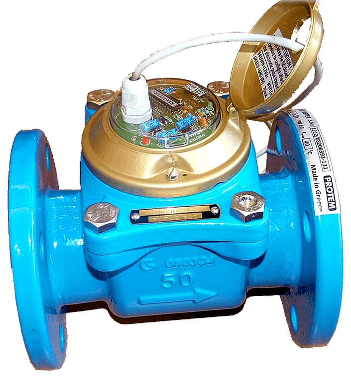
Particularly for concrete batching plants, our water meters are a very cost-effective solution compared to the installation of a scale since they provide the measuring accuracy required by the regulation. Available dimensions from 2 "to 4" with selectable electrical pulse output per 1, 2, 5 or 10 lt.
PROTEM’s water meters are WOLTMAN type with horizontal impeller, flanged, dry type, with an electronic pulse transmitter but without a reading counter. The transmission of the movement from the impeller to the pulse transmitter is done by a magnetic coupling. The impeller as well the pulse transmitting mechanism can be easily replaced without the need to remove the body of the meter from the pipelines. They are capable of smooth operation at ambient temperatures from 0° C to 60° C and a maximum water temperature of 40° C.
ADVANTAGES
The PWM II water meter series feature:
- Microprocessor based pulse transmitter with fuzzy logic error detection. This solves the most common problems that other water meter in the market are facing:
a) False pulses due to the hydraulic shock, reverse water flow or vibrations in the water pipelines.
b) High resolution (1lt/pulse) even on large flow rates.
c) Led indication of output pulses and permitted flow rate exceeded.
- Magnetic coupling between impeller and electronic metering head. This means that no sensitive part of the meter comes in contact with the water, except its impeller.
- Easy access to the impeller without the need to disconnect the meter body from the pipelines. Consequently, the maintenance of the water meter and the cleaning by foreign objects that can block the impeller becomes very fast.
AVAILABLE MODELS - TECHNICAL SPECIFICATIONS
| Nominal Diameter of PWM II | mm | 50 | 65 | 80 | 100 |
|---|---|---|---|---|---|
| in | 2’’ | 2 ½ ’’ | 3’’ | 4’’ | |
| Flow specifications | |||||
| Nominal flow rate according to ISO 4064 | m3/h | 15 | 25 | 40 | 60 |
| Maximum flow rate Qmax | m3/h | 70 | 100 | 150 | 250 |
| Maximum working flow rate | m3/h | 35 | 50 | 90 | 125 |
| Flow division limit Qt | m3/h | 2 | 5 | 6 | 6 |
| Minimum flow rate Qmin | m3/h | 0.7 | 0.75 | 0.8 | 1.2 |
| Flow rate at pressure drop 0.1 bar | m3/h | 38 | 65 | 75 | 100 |
| Accuracy within Qmax - Qt | % | ± 2% | ± 3% | ||
| Accuracy within Qt - Qmin | % | ± 5% | |||
| Dimensions and weights | |||||
| Length of embodiment | mm | 200 | 200 | 225 | 250 |
| Total height | mm | 220 | 230 | 240 | 255 |
| Exterior flange diameter | mm | 165 | 185 | 200 | 220 |
| Weight | Kg | 11 | 12 | 15 | 17 |
| Standard flange drilling according to DIN 2532 and BS 4504 | |||||
| Electrical output specifications | |||||
| Rated supply voltage | 8-24 VDC | ||||
| Output signal | Transistor out NPN, 70mA max. | ||||
| Protection | Overload, short-circuit | ||||
| Resolution (Lt/pulse) | 1, 2, 5, 10 (selectable) |
Photos
Related products
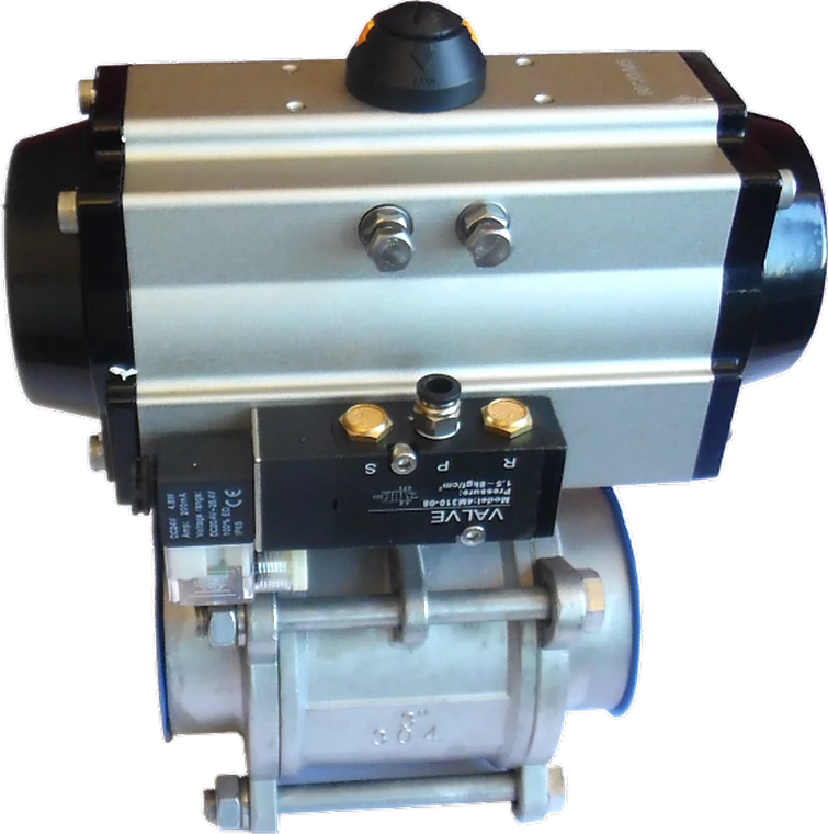
Automatic Ball Valve
Ball valves with pneumatic drive are used in the building materials industry for the…
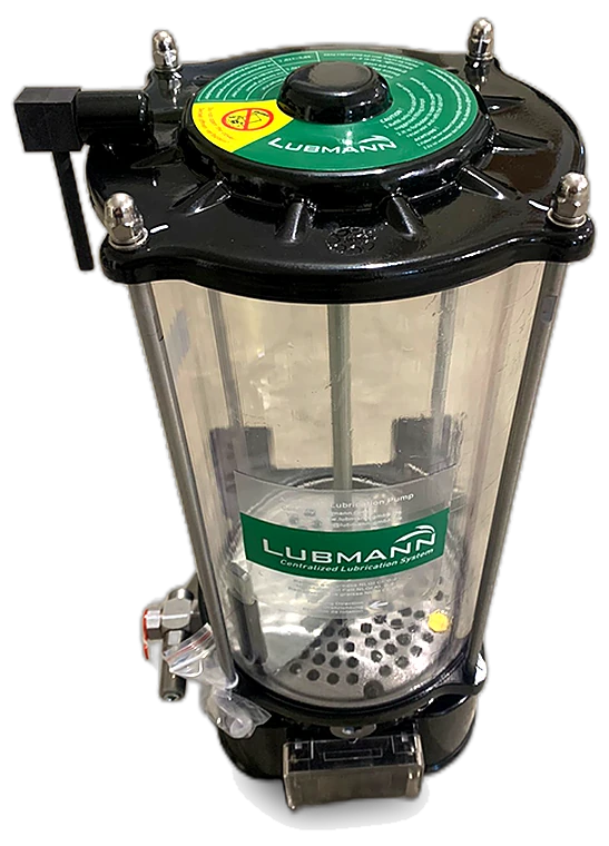
Automatic Lubrication System
In the field of construction machinery, the value created by the installation of an…
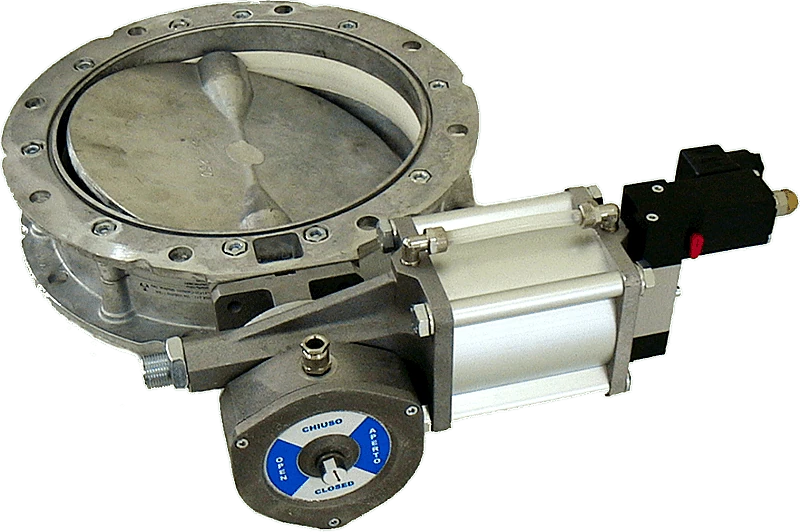
Butterfly Valves
Butterfly valves are widespread in the industry, especially in the construction material…
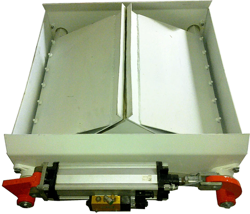
Hopper Gates
They are used in hopper outlets - silos of aggregates or other coarse materials when the…
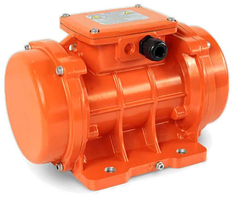
Industrial Vibrators
Protem Group provides a wide variety of OLI electric industrial vibrators, part of WAM…
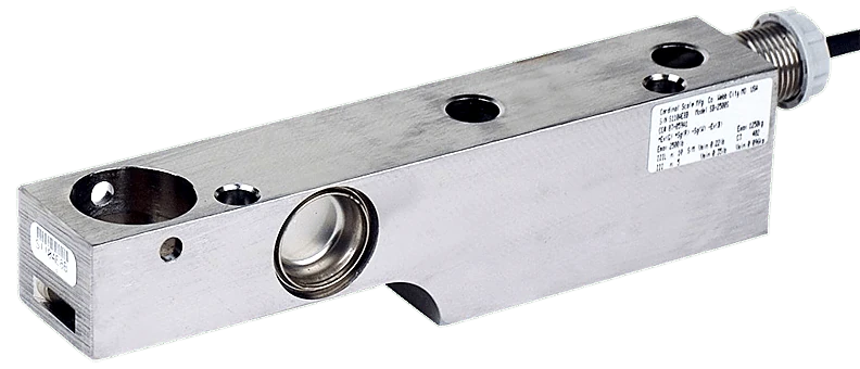
Load Cells
Cardinal’s model SB shear beam load cells promote a variety of applications, such as…
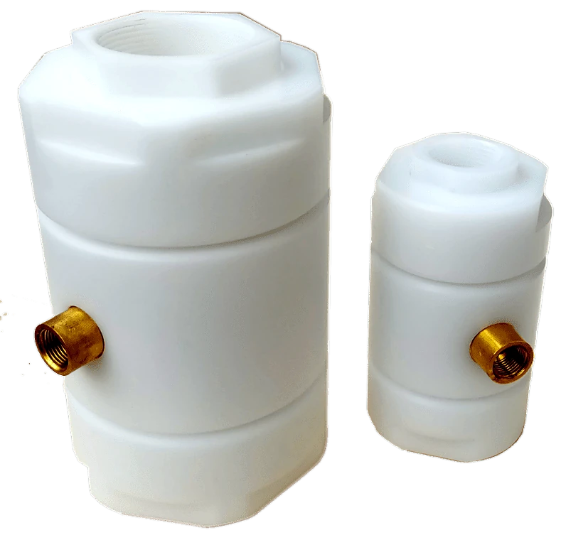
Pinch Valves
Pinch Valves are suitable for dust, granular or pulpy medium as well as for liquid or…
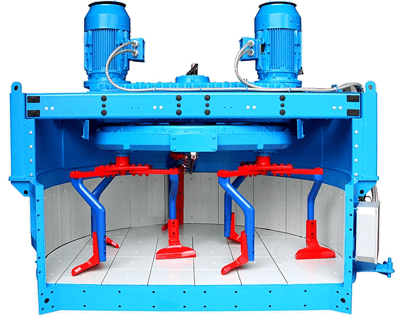
Planetary Mixers
Vertical shaft mixers, also commonly known as planetary mixers, are best suited for…
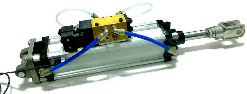
Pneumatic and Hydraulic Pistons
We can provide you with pneumatic pistons for the aggregate shutters or waiting hopper,…
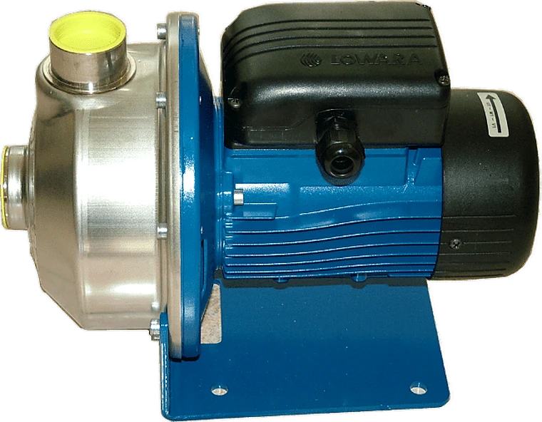
Pumps for Water and Additives
We study the actual needs of your factory and provide you with the right pump. Whether it…
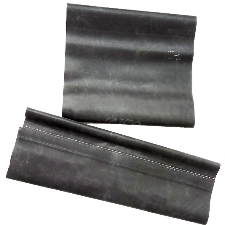
Rubber Joints
PROTEM provides rubber joints made of soft material for the connection of screw conveyors…
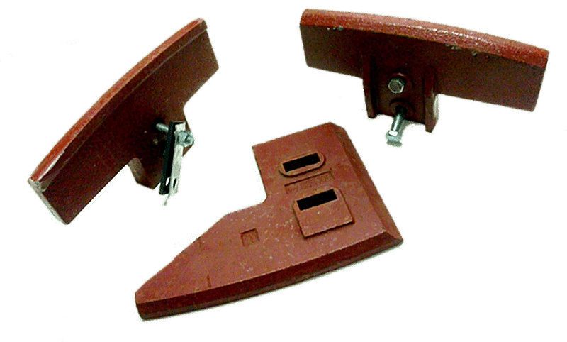
Spare Parts for Mixers
Genuine spare parts and consumables for twin shaft, planetary and vertical shaft mixers…
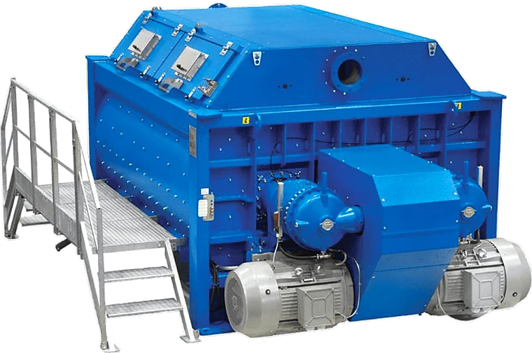
Twin Shaft Concrete Mixers
Double horizontal shaft mixers are the most suitable for the ready-mix concrete industry…
Open to new challenges
Connect with us
Do you prefer live communication? So do we!